The tutorials part 6 for the Android version of Cargo Surveyor deals with the Ullage report.
Recently we discussed the fifth document of the set of documents required to be produced in the load port, the VEF report.
Today we will discuss part 6 of the tutorials, which will deal with the ullage report:
Cargo Surveyor is designed with user convenience and flexibility in mind. The app being used primarily on oil tankers and chemical tankers, we have chosen to give the user two different option sets regarding possible tank configurations:
- a standard layout, which accommodates a minimum of 12 tanks (5 pairs of wing tanks plus two slop tanks) and 3 bottom lines, and a maximum of 23 tanks (7 crosses plus two slop tanks) and 3 bottom lines.
- An extended layout, which accommodates a minimum of 34 tanks (16 pairs of wing tanks plus two slop tanks) and 3 bottom lines, and a maximum of 50 tanks (16 crosses plus two slop tanks) and 3 bottom lines.
The bottom lines and slop tanks can be used in any way the user wants to, they are simply considered as tanks just like the other tanks. (Not to be confused with actual bottom lines, which can either be included or excluded from tank tables). There are times however that the bottom lines L1, L2 and L3 are used to either add or deduct volume of cargo for a selected grade, and this depends indeed on whether bottom lines on the vessel are included in tank calibration tables or not, and what the grade of each bottom line is. More on this later.
When you open the app, the first screen that always appears is the layout selection screen, where you will be asked to choose between either the standard or the extended layout:


In the top right hand corner of this screen is also an options menu button, that will let you straight go to general settings etc.
For our testship, being a vessel with 6 pairs of wing tanks and 2 slop tanks (plus a residual oil tank), we will select the STANDARD layout. As soon as we press the button (‘USE STANDARD LAYOUT’) we are presented with the standard layout tank configuration editor:

At present only the ‘Open file’ button is enabled, all other buttons are disabled. If you previously created an ullage report than you can open that ullage report for editing by pressing the ‘Open file’ button and selecting the ullage report from the list of available reports. In our case we are going to create a new report from scratch so first we need to select the appropriate tank configuration; as soon as you press ‘Select tank configuration’, a pop up window appears where you can select a possible configuration. In these tank configurations slop tanks and bottom lines are not mentioned since they are always included:

For our testship we need to select ‘6W’: this will create an ullage report with 6 wing tanks + 2 slop tanks + 3 bottom lines. As soon as you press ‘6W’ on the drop down list in the above picture, you will notice that now all buttons 1-6P, 1-6S, Slop P, Slop S and L1, L2 and L3 buttons are enabled, as well as the ‘New File’ button.
We now press the ‘New File’ button; in the new window where we are asked to enter a file name, we can enter ‘Testship’ and press ‘OK’:

We are now taken directly to the tank editor (standard layout), with the new ullage report already created and opened and tank 1P selected:
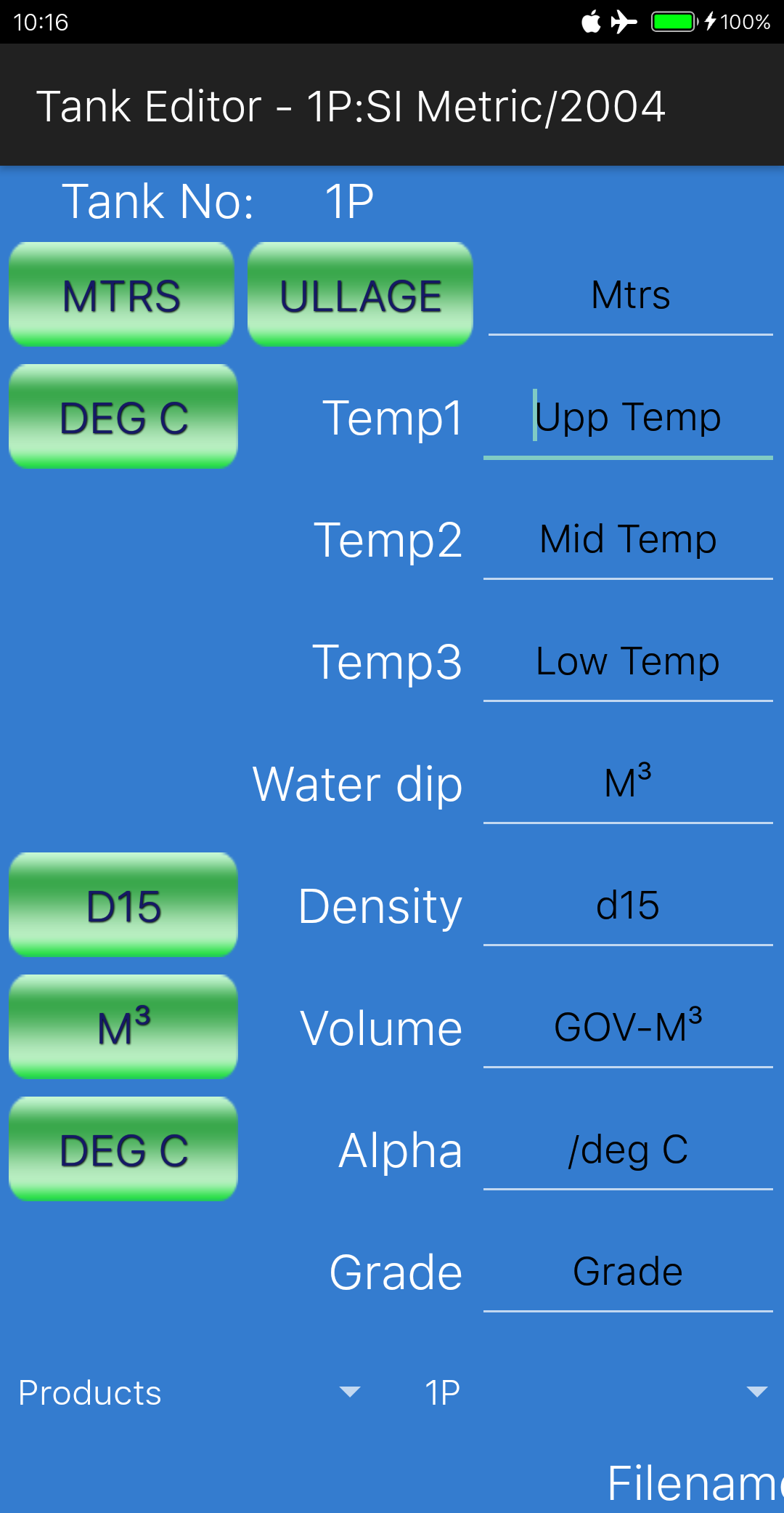
Within the tank editor, the first thing we see in the top of the screen is 1P:SI Metric/2004. 1P is the name of the selected tank in the list of available tanks. SI Metric means that in general settings SI Metric units has been chosen, and 2004 indicates that ASTM 2004 tables have been selected.
There are five buttons on the screen for switching units (no.6 button ‘ULLAGE’ is only to indicate whether ullage or innage is being used, but presently this is not reflected in the actual report):
– ullage between meters and feet / inches: you can select this unit for each tank individually; this is handy in case the vessel has ullage tables using feet and inches while you want to make your report in metric units: first press the ‘MTRS’ button, so that the input changes to feet, inches. The title of the button now changes to ‘FT,IN’. Now enter the ullage (say for example ‘7, 8.5’). Now press the ‘FT,IN button again, and the ullage is automatically converted to 2.350 mtrs.
– temperature between deg C and deg F: same as with ullages, you can select the unit for each tank individually and convert between deg C and deg F with the press of a button, in this case the ‘DEG C’ button below the ‘MTRS’ button.
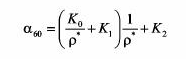
– density between density @ 15 deg C and API at 60 deg F: as with the other units, if you press the D15 button, the density (if you have entered one) will be automatically converted to API and the title of the button changes to ‘API’.
– volume between M³ and Bbls: likewise, if you press the M³ button, any volume you have entered will be converted to Bbls, and the title of the button will change to ‘BBLS’. Both volume in the volume field and the water dip field will be converted.
– thermal expansion coefficient (Alpha) between /deg C and /deg F: if you press the ‘DEG C’ button (below the M³ button), the expansion coefficient will be converted to /deg F.
All these units (except ullage) will be converted to the selected standard in the general settings when you generate the pdf report: if in general settings you have selected ‘SI Metric’, then all values will be printed in metric units, and if you have selected ‘Imperial’, then all values will be printed in imperial units.
Ullages however, will be printed depending on one particular setting in the pdf report settings: at the bottom of the pdf report settings there is an entry called ‘Keep ullages in original units’:

If this option is ticked, then ullages will be printed based on the ullage unit that has been used for the first tank: if the ullage of 1P is entered as ‘feet, in’ then all ullages will be printed in feet and decimal inches, regardless of whether you have selected metric or imperial units.
On the right hand side of the screen are fields to enter ullage, a maximum of three temperatures, the volume of any water in the tank, the density in vacuum at 15 deg C (or the API at 60 deg F), the tank volume, alpha (in case of special applications using table 54C or 6C and in case of chemicals), and the name of the grade.
If you have selected ‘Chemicals’ as cargo type, there is one additional field called ‘at temp’: here you can enter the temperature for the observed density (see below). Also the density button is disabled and will now have as title ‘DENSITY’ instead of ‘D15’. When chemicals is selected as cargo type, it is not possible to change the density unit to API.
At the bottom of the screen is the drop down to select the tank for which you want to enter data, currently pointing at 1P; to the left of the tank drop down is the cargo type selector, which you can set to either:
– Products
– Crude
– LubOil
– Special Applic(ations)
– Chemicals
If you select any cargo type except ‘Chemicals’, the ASTM tables are used for calculating the weights, VCF etc. In the case of Chemicals (not to confuse with ‘Special applications’) , the density is entered as observed density, together with a corresponding temperature for that density. In this case the ‘at temp’ and Alpha are used to calculate the actual weight in air. No GSV can be calculated since many chemicals such as FAME / vegetable oils are not even liquid at 15 deg C.
For all other cargo types the normal ASTM tables are used; which table is used for calculating the VCF depends on:
– The cargo type: if ‘Products’ is selected, either table 54B or 6B is used, if ‘Crude’ is selected, either table 54A or 6A is used etc.
– Whether in general settings ‘SI Metric’ or ‘Imperial’ has been selected; if Imperial is selected table 6B is used, if SI Metric is selected table 54B will be used. The same applies for Crude, LubOil and Special Applications.
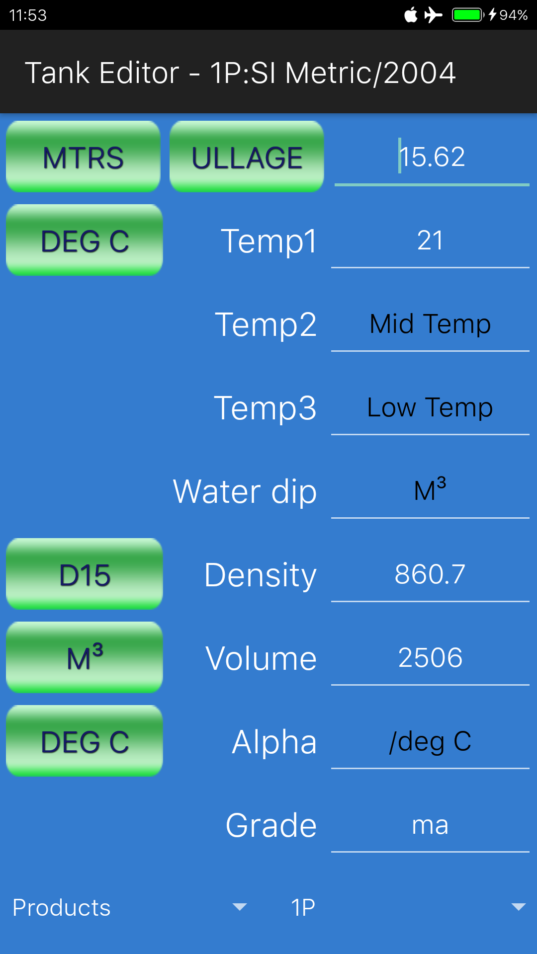
Let us now enter an example referring to the screen shot below:
Testship will load the cargo of mixed aromatics in various stages, receiving parcels with different densities from different shore tanks.
Each parcel will be loaded evenly across all tanks so as to achieve a homogeneously commingled end product.
As can be seen in the picture on the left, we have entered an ullage of 15.62 mtrs, a temperature of 21 deg C, a density in vacuo at 15 deg C of 860.7, a volume of 2506 M³ and the grade name ‘ma’.
This grade name is arbitrary, you can enter any name you wish, as long as you ensure that this grade name is exactly the same for each tank carrying this grade, because the calculation of totals per grade is dependent on the grade name.
Now if you press the back button and return to the tank configuration screen, and then press the ‘1P’ button, you will see not only the info that we have just entered but also the VCF, GSV, MTons in air/vacuum, LTons, Bbls and Gallons are all displayed for this tank.
In the bottom of the screen the title of the report, as well as the grade name are displayed in an animated scrolling text field:

Phew! It has been a pretty long session already! We will take a break here, and discuss the remainder of the ullage report session in the next tutorial, part 7.
In the mean time, for those who are interested in Cargo Surveyor for Android: the app can be downloaded here:
We post updates for the app in Google Play frequently to solve minor bugs, and advise all users to update as soon as a new update is available; we don’t use advertisements in Cargo Surveyor and we never will.
If you have any queries, suggestions, comments, criticism about the app or this blog post, please let us know! We always do our best to accommodate any requests for additions/modifications to our apps if they improve the value!